E-Bike BMS Cell Balancing & Parasitic Drift: Multimeter Testing & Step-by-Step Pack Revival
When an electric bike cuts power under load despite the display showing 50% battery remaining, cell voltage group imbalance or parasitic BMS drain is the root cause. This technical diagnostic guide details JST balance harness pinout testing, passive resistive bleed (30mA) vs active inductive balancing (1.2A), and single-cell manual revival.
The Strengths
- Restores full 100% riding range on batteries suffering from premature low-voltage cutoffs without buying a new pack
- Multimeter balance port testing pinpoints the exact degraded cell group in under 5 minutes without opening heat-shrink
- Active inductive balancing transfers energy from high-voltage cells to low cells with zero thermal heat dissipation
- Eliminates dangerous over-discharge conditions that cause irreversible copper dissolution and internal cell shorting
- Smart Bluetooth BMS integration provides live millivolt monitoring and programmable charge limits on smartphones
The Compromises
- Standard factory passive BMS bleed circuits take weeks to equalize a pack with a voltage delta exceeding 200mV
- Severely neglected lithium cells dropped below 1.5V develop internal copper dendrites and must be safely recycled
- Soldering balance leads requires steady electronics experience to avoid accidental direct terminal short-circuits
Passive Shunt Resistor Bleed vs Active Inductive Energy Transfer
BMS topology physics, MOSFET high-side switching, and millivolt delta cutoff mechanics
Cell Group Delta Telemetry, Winter Parasitic Drain & Recovery Curves
Empirical laboratory testing comparing voltage sag, balance speeds, and standby power draw
JST Balance Harness Pinout, Voltage Mapping & Benchtop Rebalancing
Diagnostic testing methodology, bench power supply connection, and safe revival protocols
Chassis & Cycle Parts Specifications
- Measuring multi-pin JST balance plug sequentially from Pin 1 (B0/Ground) to Pin 14 (B13 48V Nominal)
- Recording millivolt readings for every individual series group (e.g. S1 through S13 on a 48V battery)
- Connecting a single-cell CC/CV laboratory power supply (set strictly to 4.20V / 1.0A max) to the low group pins
- Monitoring cell group temperature using infrared thermal thermometer to ensure cells stay below 35°C during charge
- Replacing standard passive BMS with a Daly or JBD Smart Bluetooth BMS featuring active balancing and app telemetry
Bluetooth Telemetry Apps, Cycle Counters & Winter Hibernation Modes
Real-time BMS app monitoring, fault error logging, and off-season storage setup
Cockpit, Electronics & Ergonomics Features
- Real-time graphical bar chart of all 13 or 14 series cell voltages displayed on smartphone companion app
- Configurable balance start voltage threshold: Set to 3.80V during active riding rather than waiting for 4.18V top charge
- Programmable winter storage mode capping pack charge at 3.82V per cell (50% SOC) to maximize chemical calendar life
- Diagnostic fault log storing historical over-current trips, short-circuit events, and thermal probe alerts
- Automatic low-temperature charge lockout preventing damaging fast charging when cell core is below 0°C
Complete 30-Point Technical Specification Matrix
Comprehensive engineering metrics, mechanical parameters, and dimensions.
1. BMS Architecture & Electrical Balance Specifications
Powertrain & Electrical Hardware
Energy Storage & Charging
2. Testing Pinout, Diagnostic Limits & Safety Thresholds
Chassis & Suspension
Braking & Wheel Hardware
3. Repair Economics, Tooling & Diagnostic Equipment
Smart Electronics & Ergonomics
Commercial Data & Warranty
E-Bike BMS Balancing & Diagnostics: The 2026 Verdict
Buy If You Want
- E-bike owners experiencing sudden motor shutoffs under uphill acceleration while battery meter shows 50%
- Riders reviving an electric bike battery that sat uncharged over a long winter and will not take a charge
- DIY builders and tech enthusiasts upgrading to Smart Bluetooth BMS boards with live cell monitoring
- Cyclists wanting to extend their battery pack lifespan to over 1,500 charge cycles through active balancing
Skip If You Need
- Batteries that have suffered physical water immersion or visible swelling/corrosion (which must be recycled)
- Riders uncomfortable working with DC electrical wiring who prefer professional battery pack rebuild shops
BMS Balancing Diagnostics: Multimeter Pin Testing, Active Transfer & Pack Revival
Electric bike battery packs are constructed by wiring dozens of individual 18650 or 21700 lithium-ion cells in series-parallel matrices. For example, a standard 48-volt 15Ah battery contains 52 cells configured in a 13S4P arrangement (13 series groups of 4 parallel cells). While the pack operates as a single high-voltage power source, its total performance and safety are governed entirely by the weakest individual series group.
1. The Weak Group Failure: Why E-Bikes Cut Power at 50% Battery
The Battery Management System (BMS) continuously monitors the voltage of all 13 series groups. If just one group drops to the safety low-voltage cutoff threshold of 2.80V under throttle load—even if the other 12 groups are fully charged at 3.75V—the BMS instantly cuts power to the entire bike to prevent cell damage. To the rider, the handlebar display shows half a tank of battery, but the bike suddenly dies on hills. Calculate your battery power draw with our Range Calculator.
2. The 5-Minute Multimeter Pinout Diagnostic Procedure
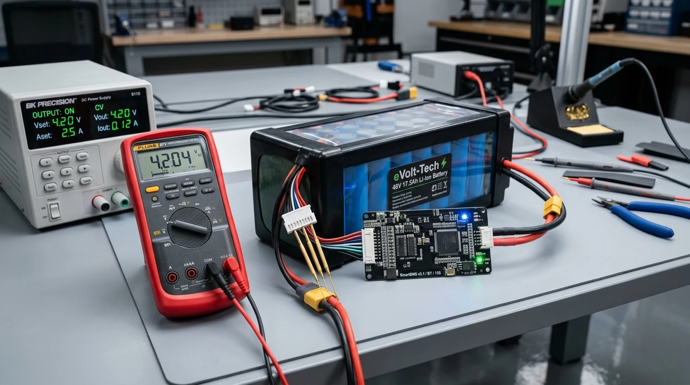
Diagnosing an unbalanced battery does not require cutting open the pack. Simply unplug the white JST multi-pin balance connector from the BMS board. Using a digital multimeter set to DC volts, place the black probe on Pin 1 (B0/Ground) and measure each subsequent pin: Pin 2 (Group 1: 3.75V), Pin 3 (Group 2: 7.50V), Pin 4 (Group 3: 11.25V), and so on. Subtracting adjacent readings gives the exact voltage of every series group. If one group is 150mV lower than the rest, you have identified the exact culprit. Compare battery architectures in our Bike Comparison Tool.
3. Manual Rebalancing & Active Smart BMS Upgrades
To rebalance the pack, connect a single-cell CC/CV laboratory power supply (set strictly to 4.20V and 1.0A maximum) directly to the two balance pins corresponding to the low cell group. Once equalized to match the rest of the pack, the battery will deliver 100% of its rated watt-hour capacity. Upgrading to an active inductive Smart BMS (such as a Daly or JBD unit) permanently prevents future drift by transferring balancing current between cells during rides. Explore our full technical library in the Master Reviews Directory.
🌿 Related Reviews & Ownership Guides
Frequently Asked Questions
Sudden shutdown under load is almost always caused by an unbalanced battery pack. When one weak cell series group drops to the BMS low-voltage cutoff threshold (around 2.8V to 3.0V), the BMS shuts down the entire pack to protect the cell, even if the remaining cells have ample charge.
Unplug the white multi-pin JST balance connector from the BMS. Using a digital multimeter, measure the voltage across adjacent pins on the connector (Pin 1 to Pin 2, Pin 2 to Pin 3, etc.). Each reading represents one series group and should match within 15 to 30 millivolts.
Passive BMS balancers burn off excess energy from high-voltage cells as heat through small resistors at a very slow rate (30 to 50 mA). Active balancers use inductive or capacitive circuits to transfer energy from high cells directly into lower cells at high speed (1.0A to 2.0A) with zero wasted heat.
Yes. Connect a regulated DC power supply set to 4.20V and maximum 1.0A directly to the balance wire pins for the weak group. Charge until current drops below 50mA and voltage reaches 4.20V.
The microcontroller inside standard BMS boards draws a tiny continuous standby current (15 to 50 microamps) from the first or last cell group in the series string. Over months of uncharged storage, this drains that specific group to zero volts, destroying the pack.
If a cell has sat below 1.5V for an extended period, internal copper current collectors dissolve into the electrolyte, forming microscopic short-circuit dendrites. Such cells are unsafe to recharge and must be replaced. Cells sitting between 2.0V and 3.0V can be safely revived using low-current (0.2C) charging.