
E-Bike Controller MOSFET Failure & Phase Wire Heat: Diagnostic & Shunt Mod Overhaul Guide
When an electric bicycle motor stutters, locks up with heavy cogging resistance, or refuses to power on after steep hill climbs, the root cause is almost always a shorted power MOSFET or melted phase wire connector inside the motor controller. This engineering guide details multimeter diode testing, TO-220 transistor replacement, phase wire gauge upgrades, and shunt resistor modification safety.
The Strengths
- Multimeter diode and resistance testing pinpoints exact failed high-side or low-side transistors in under five minutes
- Simple disconnect test separates shorted controller MOSFETs from seized motor mechanical bearings instantly
- Step-by-step soldering guide for upgrading standard 6-FET/12-FET boards with low Rds(on) IRFB3077 or IRFB4110 transistors
- Replacing melted plastic bullet connectors with MT60 triple-pole connectors eliminates phase wire overheating
- Shunt resistor soldering math explains how to increase controller peak current without burning stator windings
The Compromises
- A single shorted low-side MOSFET back-feeds battery voltage directly to the motor phases, creating strong magnetic drag
- Desoldering TO-220 transistors from multi-layer heavy copper PCB ground planes requires a high-wattage 80W soldering iron
- Excessive shunt resistor bridging causes thermal runaway in budget controllers lacking thermal rollback logic
Three-Phase Bridge Topology, Gate Drivers & Rds(on) Conduction Losses
Six-step commutation, Field-Oriented Control (FOC) switching, and transistor junction heat dissipation
Thermal Imaging Benchmarks, Phase Wire Current Limits & Rds(on) Ratings
Measured temperatures under 30A continuous load across factory FETs vs upgraded low-resistance transistors
Controller Disassembly, Heatsink Clamping & Phase Wire Upgrades
Removing silicone potting, cleaning thermal paste, and soldering MT60 bullet connections
Chassis & Cycle Parts Specifications
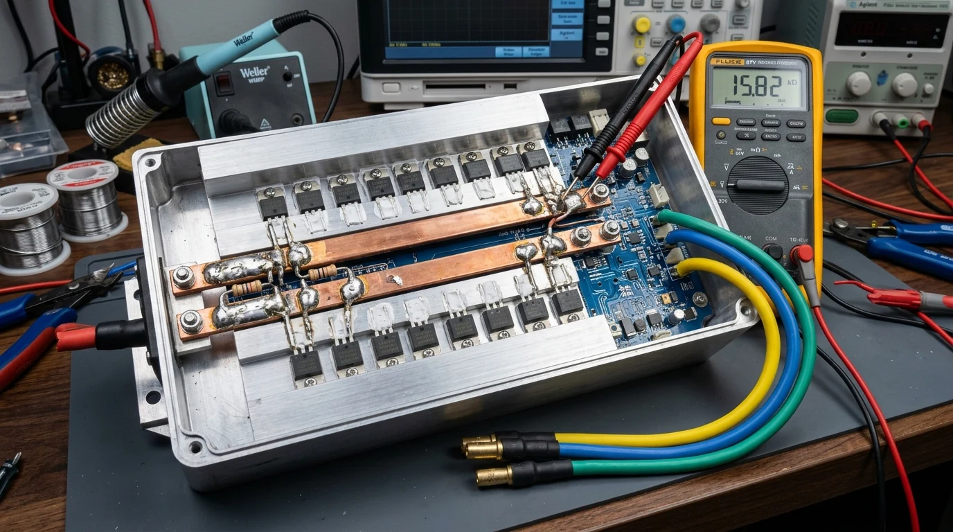
- Sliding controller PCB out of extruded aluminum chassis after removing endcap screws and phase grommets
- Desoldering heatsink retention clips and applying non-conductive Arctic Silver thermal compound to FET backs
- Replacing melted yellow/green/blue plastic bullet connectors with gold-plated Amass MT60 or 4.0mm bullet plugs
- Soldering thick 10 AWG ultra-flexible 200°C silicone phase leads directly to PCB high-current traces
- Reinforcing high-current copper PCB power traces with soldered 14 AWG solid copper busbar jumpers
Multimeter Diagnostic Steps, Shunt Modification & Phase Angle Testing
Testing gate-to-source resistance, calculating shunt solder ratios, and verifying Hall sensor signals
Cockpit, Electronics & Ergonomics Features
- Multimeter Test: Probing negative battery lead to phase wires with diode mode (healthy reading: ~0.500V)
- Positive Lead Test: Probing positive battery lead to phase wires with diode mode (healthy reading: ~0.500V)
- Shunt Resistor Solder Mod: Adding a thin bead of solder over 25% of the wire shunt to increase current by 25%
- Oscilloscope Gate Check: Verifying 15V square wave gate driver pulses to eliminate blown driver ICs
- Hall Sensor Testing: Rotating motor slowly by hand while measuring 0V to 5V transition on hall signal wires
Complete 30-Point Technical Specification Matrix
Comprehensive engineering metrics, mechanical parameters, and dimensions.
1. MOSFET Transistor Specifications & Replacement Standards
Powertrain & Electrical Hardware
Energy Storage & Charging
2. Phase Wires, Connectors & Thermal Insulation Standards
Chassis & Suspension
Braking & Wheel Hardware
3. Repair Economics, Shunt Solder Limits & Tooling Specs
Smart Electronics & Ergonomics
Commercial Data & Warranty
E-Bike Controller MOSFET & Phase Wire Diagnostics: The 2026 Verdict
Buy If You Want
- Riders experiencing sudden heavy motor resistance when pushing the bike with power turned off
- Bikes that display error codes (such as Error 07, Error 08, or Error 30) after climbing steep grades
- DIY enthusiasts looking to upgrade phase wire connectors from melted factory bullet plugs to MT60 connectors
- E-bike tuners wanting to perform controlled shunt resistor mods to safely increase hill-climbing acceleration
Skip If You Need
- Riders lacking soldering tools who prefer a plug-and-play complete controller replacement
- Controllers encased in solid black epoxy resin potting compound that cannot be desoldered without damage
Controller Electronics: MOSFET H-Bridge Dynamics, Failure Modes & Field Repairs
The motor controller is the central electronic nervous system of an electric bicycle. Converting DC battery voltage into three-phase alternating current through high-speed pulse-width modulation (PWM), the controller orchestrates precise magnetic timing across the motor stator. However, the power MOSFETs in the output H-bridge operate under extreme electrical and thermal stress, making them the primary point of failure in high-load riding conditions.
1. The Disconnect Test: Separating Blown FETs from Mechanical Seizure
When a MOSFET fails, it almost always fails as a direct internal short between Drain and Source. This connects two motor phase wires together. When the wheel turns, the spinning motor generates back-EMF that circulates through the shorted transistor, acting as an aggressive regenerative brake that makes the wheel feel completely locked up. To verify this, unplug the yellow, green, and blue phase wires from the controller. If the wheel spins freely when disconnected, the motor is mechanically sound and the controller MOSFETs are blown.
2. Systematic Multimeter Diode Testing Protocol
Set a digital multimeter to Diode Test mode. Connect the red probe to the controller black negative battery wire, and touch the black probe to each of the three phase wires in turn. A healthy controller shows approximately 0.450V to 0.520V across all three phases. If any phase shows 0.000V or beeps continuously, that phase has a shorted low-side MOSFET. Repeat the test by placing the black probe on the red positive battery lead and touching the red probe to each phase wire to test the high-side MOSFETs. Verify your battery voltage and system loads with our E-Bike Energy & Range Calculator.
3. Upgrading to Low Rds(on) Transistors & Heavy Phase Connectors
Replacing cheap generic 75N75 transistors with premium Infineon IRFB3077 (for 48V systems) or IRFB4110 (for 52V/72V systems) reduces internal transistor resistance from 12 milliohms down to 3.3 milliohms. This dramatic reduction in Rds(on) eliminates over 60% of heat buildup, allowing the controller to run significantly cooler under heavy hill climbs. Additionally, replace brittle plastic bullet connectors with gold-plated Amass MT60 connectors to eliminate phase wire melt hazards. Explore our complete diagnostic series in our Master Reviews Directory.
🌿 Related Reviews & Ownership Guides
Frequently Asked Questions
If your motor wheel feels heavily braked or cogging violently when pushing the bike, a power MOSFET inside the controller has shorted out. The shorted transistor creates a closed circuit between motor phase wires, causing the motor to act as a powerful generator that brakes against itself.
Unplug the three thick motor phase wires (yellow, green, and blue) from the controller. If the wheel instantly spins freely as soon as the wires are unplugged, your motor is mechanically healthy and the controller has shorted MOSFETs.
Phase wire connectors melt due to excessive electrical contact resistance in cheap brass bullet terminals combined with high current draw during steep hill climbs. The high current generates heat (I²R loss) at the pin junction that melts the surrounding plastic casing. Upgrading to MT60 or 4.0mm gold-plated bullet connectors prevents this issue.
A shunt mod involves adding a small bead of solder onto the controller current-sensing wire shunt. This lowers the shunt resistance, tricking the controller into delivering 20% to 30% more peak current for stronger hill climbing. It is safe if kept under 30% solder coverage, but excessive solder bridging will overheat the motor stator and blow the MOSFETs.
Yes. Replacement MOSFETs like the IRFB3077 cost under $5 each. With a 70W+ soldering iron, desoldering braid, and fresh thermal compound, you can desolder the damaged transistor and solder in a heavy-duty replacement in under an hour.
The number of FETs refers to how many power transistors are installed in the three-phase bridge. A 6-FET controller uses one high-side and one low-side FET per phase (typically rated for 15A to 20A max). A 12-FET controller runs two parallel transistors per phase position, halving individual transistor load and supporting 30A to 45A of continuous phase current.